We will be debuting our new look on Tuesday morning so please join us then. 440 Super J-Pole Antenna by KA0NAN April 1996.
Dual Band Vhf Uhf Twinlead J Pole Antenna Pdf Notes 201903101154 1
Don Murray W9VE Building a Dual-Band Antenna Mentorfest 102304 16 An Even Better J-Pole - Electrically The gain is about 74 dBi.

. V1 12 November 1992 r2 W. The idea of a folding version of the copper antenna appealed to me. 52 MHz 146 MHz 446 MHz 915 MHz.
220 Super J-Pole Antenna by KA0NAN May 1996. Copper Cactus 2m J-Pole by KE7AX February 1992. The J-Pole antenna became so popular in the VHF band because of its simplicity in design and construction.
Other very good J antenna designs published in 73 Magazine have been. The Yagi J-Pole and NVIS Dipole And a glance at Antenna Design using 3D EM Software Brian Mileshosky N5ZGT High Desert Amateur Radio Club 15 Feb 2013. The antenna plans includes design dimensions for 2 meters 220MHz 440MHz and.
Parts needed 10 ft of ½ copper pipe 3 T Fittings 3 M to F 90 degree elbow fittings 1 reducing fitting 3 feed lines of 50 ohm coax V. 6 J POLE ANTENNA. However if mounted outside then an earth ground to the conduit is recommended.
Around plans for a simple J-Pole. Simple J-Type 10m Vertical by W6IOJ Sept. This designs measurements are specific for the frequency ranges indicated previously The design can be changed for resonance by altering the.
Average gain with a 2 meter J-Pole is about 3 db. Benefits - Ground plane independent - Simplicity - Built in triplexer effect 3 feed lines - Simultaneous transmission - No Bleed over between bands - Assumed gain. For 2 meters the coil is 4 turns of coax at 5 inches in diameter.
The Tri-band J-pole by KB6EPO III. The MARSians mass produced this antenna during the VHF frenzy in the mid-80s. This antenna can be rolled up for easy portable use and will outperform a rubber ducky.
DBJ-UHF was developed from a grant from AC Daughty to develop a low cost medium gain MESH antenna for UHF. This picture shows that the base of the antenna is mounted flush to the top of the mast. 220 MHz not only has repeaters but has become a.
Copper Dual-Band Super J-Pole Antenna by KA0NAN April 1993. The J-Pole antenna can be best described as a ½ wave vertical with a ¼ wave matching stub. I went to the local lumberyard and hardware store a home building supply will work as well A Backpackers Delight The Folding J-Pole A new twist on the old J-pole.
Please excuse us while we update our home page and membership management systems. The cost to build this antenna is less than 2. Terrestrial television is broadcast on frequencies from about 47 to 250 MHz in the very high frequency.
Indeed although many folks like to. A J-pole antenna K4KRW Collinear J-Pole Bob K9TMUs Slim Jim Variation on J-pole dual band easily built from a piece of 450 ohm ladder line. Kinsner VE4WK J-POLE ANTENNA FOR 2m 3 of 3 1 2 3 4 5 6 7 8 E D C B A E D C B A 1 2 3 4 5 6 7 8 5 June 1992 J-POLE PARTS LIST PROCEDURE P2 M1.
From the book the slim JIM was developed based on the basic J-Pole design see Fig1. Most notably the antennas used on the Zeppelin dirigibles. The most recent antenna I replaced with a J-pole was a 2 meter see figure 1b aluminum base station commercially built amateur antenna purported to have more than 3 db gain over a dipole.
A 6 Meter J-Pole Antenna Author. Commercial collinear base antennas multiple ⅝ wave elements means more gain lower takeoff angle. This value is about 23-24 dB higher than the average gain of a single-radiator J-pole.
On most of the J Pole designs out there a choke should be used as close to the feedpoint of the antenna as possible to help prevent rf on the feedline and creating difficulty with SWR readings. 522004 43307 PM. J-Pole Antenna Plans printable PDF format 800 kb This is a flexible antenna that is easy to build inexpensive and very handy to have in your emergency communications kit.
The J-pole I replaced at node K4ABT -7 alias 007 has increased the average signal at fifteen 15 miles by more than 5 db. There was a simple way to convert a 2 meter J-pole into a dual band J-pole DBJ-2 was developed from the successful performance of the DBJ-1 but folks requested a portable version. DINENSIONS ARE FOR 51.
We thought some of you may be interested in it. Super J-Pole Antenna This antenna was developed by the Independent Repeater Association in Des Moines Iowa for use on its many repeaters nodes and BBS. Thank you for visiting the ARRL website.
If installed per the dimensions above the antenna should have an SWR of less than 151 at both 146 and 444 Mhz. Building the Antenna I like the copper J-pole so I started a design using that antenna as a model. This is important because if the mast extends above the antenna ground plane it will affect the performance of the antenna.
Many old-timers call the J-Pole an end-fed Zep as it is similar in design to the end-fed antennas of the 1930s. This antenna does not need a ground to operate correctly. CB Antenna mounts SO-239 to 38-24 adapter 300Ω TV twinlead.
A television antenna TV aerial is an antenna specifically designed for use with a television receiver TV to receive over-the-air broadcast television signals from a television station. Television reception is dependent upon the antenna as well as the transmitter.
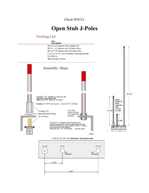
Open Stub J Poles Cascade Amateur Radio Society
2
.gif)
Antenna Projects
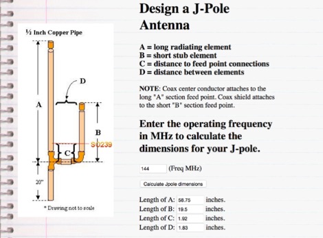
Design A J Pole Antenna Resource Detail The Dxzone Com
J Pole Antenna Design Calculator By K4abt
2

J Pole Antennas Ham Radio Ham Radio Antenna Antennas

Pdf Analysis Of J Pole Antenna Configurations For Underwater Communications Semantic Scholar
0 comments
Post a Comment